Modifying a Dillenger RPAS sensor
I got an electric conversion kit for my bike at the end of the last year. It’s fantastic — I’m riding heaps more and loving it! But unfortunately I had a lot of difficulty making it fit my bike — e.g. the manual mentioned “file off a thin layer of paint” to make the new axle fit in the front fork, but it ended up requiring the dremel.
The main difficulty though was the pedal assist. The way it works is a disc with 12 magnets is attached to the crank and they rotate past a hall effect sensor when you pedal. Dillenger calls it the RPAS. The disc comes in two halves and is held tight on the crank by a metal ring around the outside. It’s a really neat design, but didn’t fit my crank.
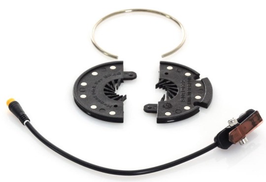
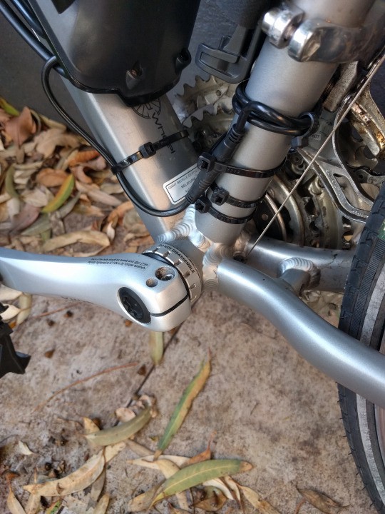
So instead I machined out the centre and attached it to the cog on the other side. You can just see it in the photo below.
Unfortunately this means that the sensor now detects pedaling backwards. Initially I thought that turning the disc to face the other way would fix it, however the way the sensor works is there are two hall effect sensors and it detects the order that the magnet passes them. It’s impossible to re-orient the sensor to make this possible.
Having it detect the wrong direction is super dangerous, so I left it disabled and forgot about it for a few weeks. However I really didn’t like riding with just the throttle because you can’t operate the throttle with your right hand and hold the handlebars properly at the same time. This resulted in an unscheduled road hugging incident.
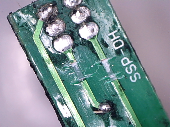
I figured I’d open up the sensor and see what could be done! Once the I’d cleaned off the potting compound, the PCB is pretty straightforward:
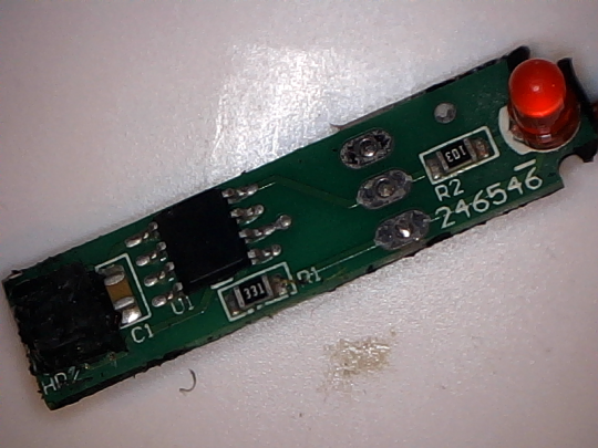
I didn’t clean the potting compound off the hall effect sensors, but there’s two on the left there next to the capacitor. They don’t appear to be the latching US1881 type that I’ve used in previous projects — both they’re oriented the wrong way for that package and the latching type would require both north and south magnets. On the disc they’re all mounted the same way.
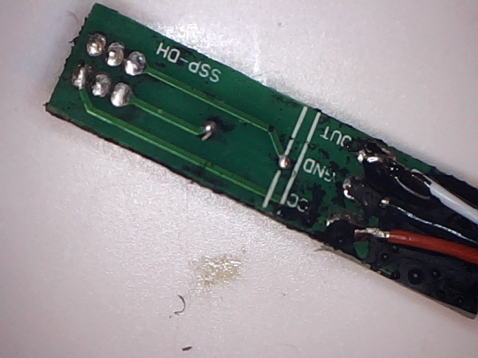
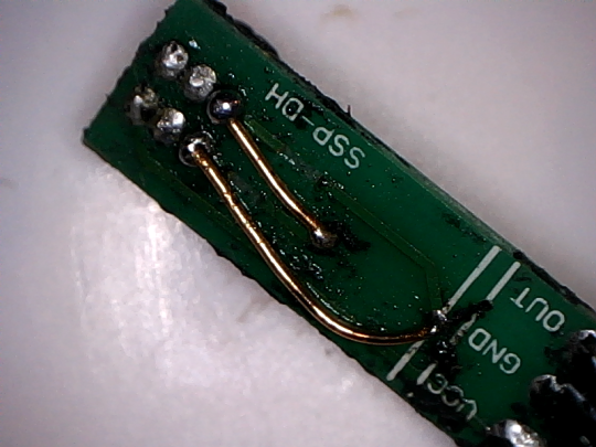
Underneath you can see the pads for the hall effect sensors and two vias. The way it works is that each time a magnet passes by the pair of sensors (in the correct direction), it toggles the output. If the magnet moves in the opposite direction, it does nothing. The LED is connected directly to the output.
The fix was pretty straightforward — invert the hall effect sensors. Two cut tracks and some enamel bodge wires, all sorted!
I repotted it in epoxy and put it back on the bike and off I went around the block with a big grin on my face.
So what’s the IC? It has no markings other than the dot for pin 1. You could implement this with a toggle flip flop, so either a “T” with Hall1->T, Hall2->CLK or a “JK” with Hall1->J->K, Hall2->CLK. But I can’t find either type in an 8-SOIC or similar. Here’s a JK type that might work but has the wrong pin positions. You could also do it with a monostable multivibrator, but the PCB doesn’t have the required passives.
My next guess would be a micro… based on the Vdd & Vdd positions, an ATTiny is ruled out, and the MSP430 has the RST in the wrong place, but the PIC12F508 seems like a good candidate?