Programming a XC9500XL CPLD with a Raspberry Pi
I have no idea why anyone would want to do this, but I have this largely-ill-conceived project in mind to make a functional CPU out of small building blocks, each implemented in a CPLD. The CPU is designed, simulated, has an assembler and a basic compiler with some simple programs. More on that later.
Update #1(several days later): After attempting to follow my own instructions I ran into some reliability problems. I found an FT232R breakout board in my parts box. So much easier, and a lot more reliable. Details at the end.
Update #2 (more days later): I built a board with several XC9572XL CPLDs on it. On this board, I had extremely limited success with any of the OpenOCD-based approaches (either on the Raspberry Pi or FT232R), however absolutely no problems with the xcs3prog approach on the Raspberry Pi, which I’ve now used hundreds of times with no issues whatsoever, with the added advantage of using the .jed file directly (skipping the .xsvf step). At some stage I’ll write a new post with details.
Step 1 — What’s a CPLD
A Complex Programmable Logic Device. It’s in some sense the pre-cursor to FPGAs, but in other ways a useful thing on their own. One of the key features of CPLDs is that they maintain their own configuration (gateware) storage — no external SPI flash required. They’re generally really small (in the order of ~100 macrocells and ~2000 gates), and don’t have higher-level features that you’d expect in FPGAs. The major FPGA vendors have CPLD product lines, although there aren’t any new revisions and they’re largely deprecated and unsupported by modern tool chains.
My goal is to emulate hard-to-find 7400 series parts, so a CPLD will do the job. Also they come in solder-able packages (e.g. TQFP44), and run at 3.3V (and have 5V tolerant I/O), and don’t need any supporting circuitry (e.g. oscillators, flash, etc).
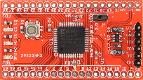
The CPLD that best seems to match my requirements is the Xilinx XC9572XL, which is handy because in a random collection of electronics that I inherited from a friend, I found this breakout board from Dangerous Prototypes (DP).
There’s a smaller (fewer macrocells) model, the XC9536XL, and there are various packages that come with more IO pins (e.g. TQFP64)
Step 2 — Making a bitstream for CPLD
It’s mostly just like an FPGA — VHDL or Verilog to bitstream to hardware programmer. Unfortunately they aren’t supported by the modern tools (e.g. Xilinx Vivado), so this is where the rabbit hole begins. This shouldn’t come as a surprise given than even the Spartan 6 isn’t supported by Vivado…
So you’re stuck with ISE (in my case, the free Webpack edition). The latest version is 14.7, which was released in 2013. It worked on (Arch) Linux last time I tried (18 months ago) but it’s now no longer functional. Fortunately, Docker to the rescue.
I’m running it in a Ubuntu 14.04 container. After following a few false starts to make this work, I ended up with a relatively straightforward set of steps based on a combination of instructions from different people. More info on my github page.
At this stage, the instructions on the Dangerous Prototypes wiki are extremely useful. After building the VHDL in ISE, you generate an XSVF file, which is basically instructions for a JTAG programmer to program the device via boundary scan. As far as I can tell, it’s not far off actually telling the programmer which bits to flip. See the DP instructions here. But in summary — after synthesising the design in ISE, use Impact (via Configure Target Device > Manage Configuration Project), then create a new project targetting XSVF, add the .jed file from synthesis, close the tab, double click the “Boundary Scan” project, then select the chip and then right click and click “One step XSVF”. Confusing!
Update: You can do the XSVF generation from the command line instead. Write a script (e.g. make-xsvf.cmd) that looks something like this:
setmode -bscan
setcable -p xsvf -file path/to/output.xsvf
addDevice -p 1 -file path/to/file.jed
program -e -v -p 1
quit
Then run it with
impact -batch make-xsvf.cmd
Much faster!
Step 3 — Programming hardware
Apparently the solution here is to use a real programmer that’s supported by Impact. But I refuse to buy another proprietary programmer that doesn’t make me at least as happy as my Black Magic Probe, so will pass on that option.
Last time I tried this, a couple of years ago, I’d used the DP instructions with a Bus Pirate (also from DP). This works, although it’s slightly annoying to have to flash alternate firmware onto the Bus Pirate, and also it’s really slow.
In this scenario, all you really need is a way to toggle JTAG pins according to the XSVF file, so any microcontroller could in theory do this, as long as it had a way to parse an XSVF file. But a good XSVF parser already exists in OpenOCD, which will run on a Raspberry Pi, and has native support for the BCM2835 GPIO. I have a $5 Raspberry Pi Zero for exactly this purpose.
Step 3.1 — Raspberry Pi as an OpenOCD programmer
I’ll write this up separately, but it’s relatively simple to set up a Raspberry Pi such that it boots and shows up as a USB Ethernet Device and CDC ACM serial port. Then it’s just a simple matter of setting up NAT on the host PC to give it internet access, and you can install OpenOCD on the Pi. In the meantime, the following two links contain most of the information:
Composite USB Gadgets on the Raspberry Pi Zero
Programming Microcontrollers using OpenOCD on a Raspberry Pi
(Use the Adafruit instructions for the OpenOCD part, but the iStickToIt instructions for setting up the USB device).
Step 4 — Using OpenOCD
From /usr/local/share/openocd/scripts/interface/raspberrypi-native.cfg you can see the pin numbering for JTAG:
# Each of the JTAG lines need a gpio number set: tck tms tdi tdo
# Header pin numbers: 23 22 19 21
bcm2835gpio_jtag_nums 11 25 10 9
Then write as simple config for the XC9572XL (e.g. xc9572xl.cfg)
source [find interface/raspberrypi-native.cfg]
interface raspberrypi-nativeadapter_khz 1000
transport select jtag
jtag newtap xc9572xl tap -irlen 8 -expected-id 0x59604093
If you’re using a different part, you can comment out the last line, let OpenOCD auto-probe, and you’ll get the correct ID. I wasn’t able to confirm that setting irlen to 8 is mandatory, I was able to make it work without that, but this at least prevents a warning from OpenOCD.
Then run OpenOCD: sudo openocd -f xc9572xl.cfg (This needs sudo because the bcm2835gpio driver opens /dev/mem read/write. You could add your user to the kmem group and chmod g+w /dev/mem but it’s easier to just used sudo on the Pi because pi is in sudoers without requiring a password).
Then connect to OpenOCD via telnet localhost 4444
Open On-Chip Debugger
> xsvf xc9572xl.tap default.xsvf
XSVF support in OpenOCD is limited. Consider using SVF instead
xsvf processing file: "default.xsvf"
XSVF file programmed successfully
>
(Note: I tried following the instructions and using SVF from Impact instead but had limited success).
And now the part that took me the longest to figure out: You need to power-cycle the CPLD to see the new gateware. For some reason, this didn’t occur to me because the sample firmware from DP(in CPLDdev.package.v1.1.zip on this page) includes working XSVF files that auto-reset after programming. Given that they were generated in 2011 using a much older ISE version, I’m guessing that something’s changed in ISE’s (X)SVF generation code. I imagine there’s an OpenOCD command that can trigger a reset via JTAG too, although everything I’ve seen so far seems to require the TRST or SRST lines.
Aside — Other options (e.g. xc3sprog)
While trying to figure out why programming wasn’t working with OpenOCD (it was, just needed reset, see above), I looked into other options, and came across no fewer than three other groups who are messing around with XC9572XLs (or other FPGAs) and Raspberry Pis.
This project uses the XC9572XL in a retrocomputing project (I came across several of these sorts of projects where CPLDs were being used). The have good instructions on using the Matrix fork of xc3sprog (see below about Matrix).
These people have built a neat little general-purpose GPIO adaptor for the Raspberry Pi, using the XC9572XL to route pins and do basic logic. Worth checking out! They’ve written their own XSVF loader. I didn’t test this, but you can read more about it here.
This is actually a really neat looking project, and they’ve done the hard work to add sysfsgpio support to xc3sprog, in their own fork (aside: both OpenOCD and xc3sprog are both still using SourceForge….unbelievable!). It’s a two year ago fork, with apparently no updates from upstream, but it does work. As far as I can tell, they use a Spartan 6, not a CPLD. xc3sprog also has the nice advantage of using the .jed file directly from ISE. I tested this out, works great, but OpenOCD is faster (possibly because it uses the GPIO directly rather than via sysfsgpio, but that’s just a guess).
I’m going to stick with OpenOCD because it’s faster and works on the upstream codebase. Update: Use xc3sprog, it works far better and uses the .jed file directly. Will write a follow-up post soon.
Update: Using an FT232R
This works much like any other FTDI-based JTAG programmer. I used the default pin assignments described here (search for ft232r).
RXD(5) - TDI
TXD(1) - TCK
RTS(3) - TDO
CTS(11) - TMS
DTR(2) - TRST
DCD(10) - SRST
The configuration looks like this. Interestingly I didn’t need the ir_len override because it now detected correctly automatically.
interface ft232rft232r_vid_pid 0x0403 0x6001
adapter_khz 4000
From memory it’s a little slower than the Raspberry Pi method, but not a big difference.