Better Bike Light Firmware Through Reverse Engineering
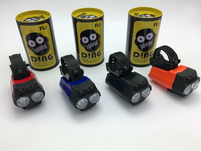
In mid-2015, I backed the “DING Bike Light” on Kickstarter. It seemed like a neat idea, Australian company, more bike light lumens more better. When it eventually arrived in mid-2017, it really lived up to the description. Awesome!
Because Eddy was riding her bike a lot more than I was at the time, I gave it to her, but then in Jan 2017 I came off my bike at a fairly high speed in the dark. In the accident, somehow the only serious damage to the bike was that my old light smashed (and it was clearly inadequate anyway!) so decided to get one for myself. By complete co-incidence, a kind friend who felt sorry for me at the time also bought the exact same light for me.
Anyway, the DING is a really good light. It’s seriously bright, the downwards facing LED is excellent for avoiding potholes and it makes me far more visible at night time. It has something like NINE (count them!) different modes. It charges over USB. They won awards!
There is only two major problems with this light:
- It doesn’t attach to the handlebars very well and tends to flop around a bit. This can be somewhat mitigated, but the rubber strap thing is definitely inferior to the fixed mounting point with a snap clip mechanism.
- There are NINE MODES. But the only mode you care about is mode 7 or 8 or something. And it doesn’t remember the mode from last time you used it. So every time you turn on the damn thing you have to do this crazy dance of pressing the tiny little button enough times to get to the right mode. Argh! It’s such a minor thing, but also it really feels like they didn’t give this much real-world testing.
I wrote to DING and asked whether, given that it had a USB port, perhaps there would be a possible firmware upgrade. I got a nice reply back but sadly no luck, but they were considering this for their next product. It’s pretty annoying to be told “hey buy a new bike light from us”.
Let’s take a brief minute to acknowledge the fact that my bike lights have firmware, but I guess it’s 2018 so that’s not so weird now. At least they’re not connected to the Internet.
So what to do! First let’s check if perhaps it has DFU (Device Firmware Upgrade) capability over the USB port. I tried a bunch of combinations of holding the button and plugging it in, but never manged to find anything that made it show up as a device. (I now know the data lines aren’t connected).
Next, let’s open it up and see what’s inside:
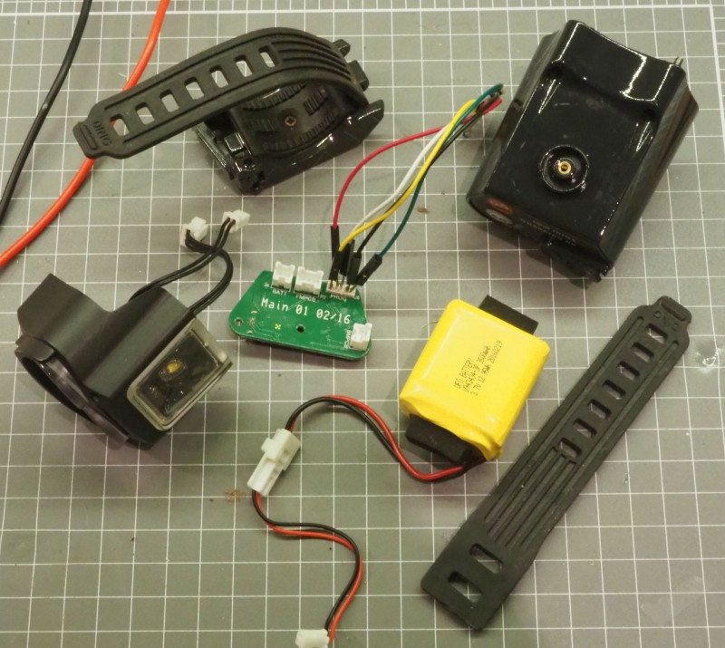
Time to try and identify some chips. Also the orange/gold coloured round thing… yeah that’s the button. I wasted ages trying to figure out what sort of crazy component that was before wondering to myself “where’s the button?”.
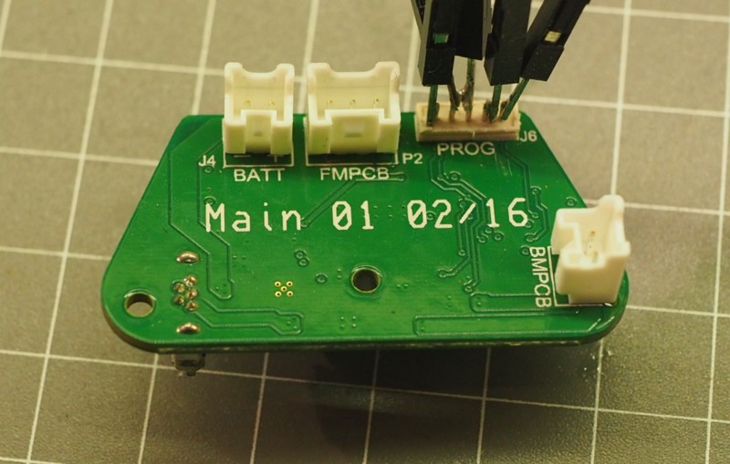
No secret “programming mode” button or switch, and looking at the traces, the D+/D- pins don’t go anywhere. Microscope time.
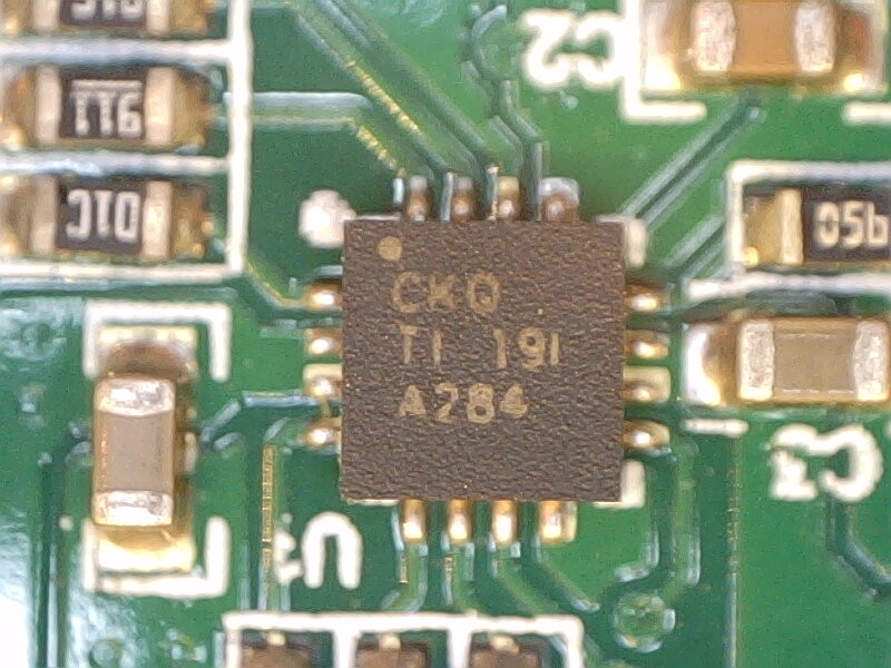
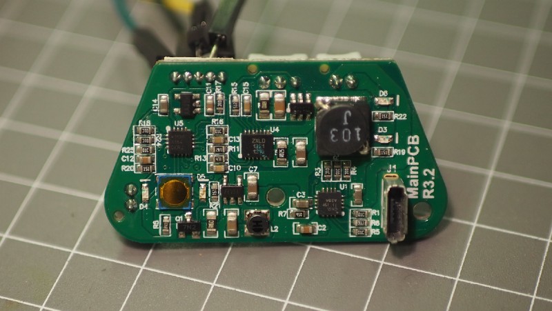
I’m fairly sure this is some sort of battery charging controller. Couldn’t find the exact part.

That’s the LED driver. Unsurprising!
The ZXLD1321 is an inductive DC-DC converter, with an internal switch, designed for driving single or multiple LEDs in series up to a total of 1A output current.
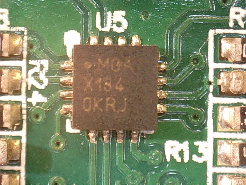
This one’s almost certainly the microcontroller. It has pins connecting to the blue/orange/red/green indicator LEDs. But what is it?
First step is to search Digikey for 16-pin *QFN package microcontrollers. That leaves you with a couple of main options: TI MSP430 and PIC16F. Both plausible, but fortunately I got lucky with the first datasheet for a PIC16F that had an example marking of:
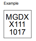
Didn’t take long to narrow it down to the PIC16F1503. Well at least it’s not an MSP430, but I’m very strongly on the AVR side of the PIC / AVR divide, almost entirely because I hate Microchip’s awful (and expensive) compilers. Seriously… $30/month for the optimizing compiler? Thank goodness it wasn’t an MSP430 and I’d have to buy yet another programmer to add to the collection.
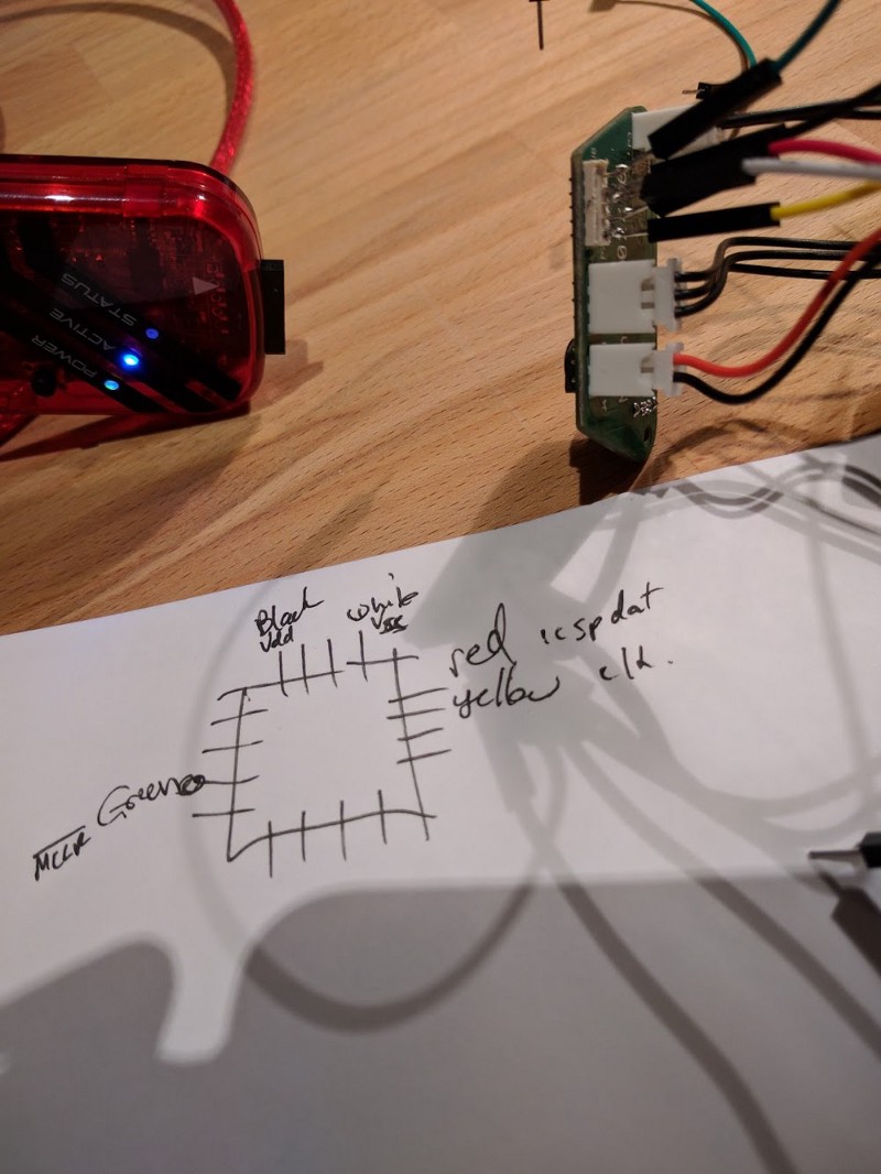
Anyway, I wired up my PICKit to the programming header and sure enough MPLABX was able to find it. Knowing the pin numbering of the PIC16F1503 made it pretty straightforward to trace the pins to the programming header and figure out the order. At this stage I was hopeful I’d be able to pull down the firmware, disassemble it and find where the “default mode” byte was and make a quick fix to make mode 7 the default. Quick check to see if the read-protect fuses were set, but of course they were.
While the read-protect fuse prevents me from reading the existing firmware, it’s possible to just write new firmware from scratch. There’s only 9 IO pins, suspect five of them are used by the button and the status LEDs. Two are probably used by the front and down LEDs. How hard could it be?
Next step was to figure out what each pin does. Watching the pins one by one with a scope while running through the various operating modes (on, charging, etc) it was straightforward to find the LED pins (especially the main front/down ones because they were PWMed). The only really tricky part was battery charging — I had no idea whether the PIC was involved in this process, but eventually was able to figure out that one pin was an analog input measuring battery voltage, and another was an output from the charger IC indicating “it’s currently charging”.
I wrote a quick program to read from the button and toggle the four indicator LEDs, then another one to measure the two battery status pins. Using the bench supply at different voltages and blinking a 10-bit binary number on the orange LED I was able to figure out sensible threshold voltages for the battery charge level.
Then setting up the PIC’s PWM controller I was able to modulate the brightness of the main front and down LEDs. Woohoo!
You can see the final firmware here — https://github.com/jimmo/ding-light/blob/master/main.c I’m not terribly experienced at using PICs so most of the time was spent remembering how to use the PWM and ADC functionality.
The new firmware implements a much less fiddly on/off sequence for the button (double-tap to turn on/off). It always defaults to “night mode” which is something a bit like mode 7 from the original firmware — always-on down LED, and a modulated front LED which does a sawtooth brightness between 100% and 50%. Asingle-tap on the button will toggle “day mode” which turns off the down LED and makes the front LED double-blink every couple of seconds.
The light goes into “dim mode” when the battery voltage dips, then finally switches itself off below a low voltage threshold.
One final thing was to enable the PIC’s low power sleep, and measure standby current with my EEVBlog uCurrent. It was low enough that the battery should last for many months. Unfortunately I didn’t measure it before with the old firmware.
This was a fun project! It felt really great to be able to fix a simple issue with a product that I otherwise like a lot. I’ll need to spend some time testing it with real-world battery discharge times to see if I got the thresholds right, but other than that I’m looking forward to flashing it onto our other two lights and hopefully getting some friends who have the same light to try it too!